Overview
As part of a university design project, I conducted a detailed case study site visit and structural investigation of the Umm Suqeim Footbridge in Dubai.
The primary objective was to perform a hands-on field survey—measuring and documenting the physical dimensions of every primary and secondary structural member, including the main truss frame, the roofing framework, and the floor decking system—to establish a structural analysis and load assessment for the bridge.
- AutoCAD
- Autodesk Inventor
- LinPro
Challenge
- Evaluating the overall load distribution and load path presented significant technical challenges, requiring precise calculation of self-weight across diverse structural profiles and materials.
- Navigating structural design standards toward the ultimate limit state design and serviceability limit states—specifically applying British Standard Eurocode 0 (BS EN 1990) Equations 6.10a and 6.10b to calculate optimal design load combinations for both permanent (dead) and variable (live) actions and finding which one gave the most critical loading scenario.

Approach
- Step 01
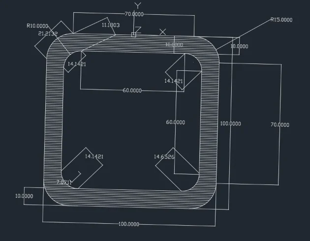
Conducted manual site measurements using physical surveying tools to determine exact cross-sectional dimensions and span geometries across all structural components.
- Step 02
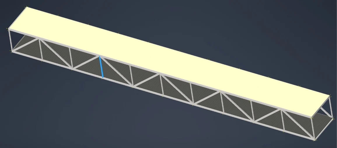
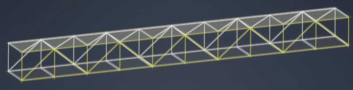
Built a detailed 3D wireframe model in Autodesk Inventor based on the measured dimensions, assigning precise material densities to determine the total volumetric and dead load weight of the structure.
- Step 03
Ensured that the section materials and cross-section members (RHS, SHS and I-Beam) were put into AutoCAD before assembling everything in Inventor.
- Step 04
Calculated dead weights into point and line loads (kN/m to kN), establishing a comprehensive loading model to simulate in LinPro structural analysis software. Finding the load path of the bridge and the load assessment of each member and system of the bridge to conduct a load assessment (dead load & live imposed load).
Outcome
- 01
Developed an exceptional, fully detailed 3D Inventor assembly of the entire footbridge structure—incorporating Rectangular Hollow Sections (RHS), Square Hollow Sections (SHS), and underlying I-beam girders supporting thin steel floor decking.
See the drawings - 02
Successfully calculated support reactions, axial forces, and member deflections in LinPro, confirming that the bridge design was structurally stable, optimized, and fully compliant with Eurocode standards.
- 03
Seamlessly combined field data, CAD parametric modeling, and fundamental structural analysis into a comprehensive engineering case study report.